Set Up TipTop According to the AO Mode
This page explains how to configure TipTop depending on the type of adaptive optics (AO) system you want to simulate — in other words, how to complete your .ini configuration file (see the Parameter files explained page for a full description of the available parameters).
AO Modes
Before diving into the configuration sections, you should first determine which AO system you intend to model. TipTop supports the following modes:
- Single Conjugate Adaptive Optics
- Laser Tomography Adaptive Optics
- Ground Layer Adaptive Optics
- Multi Conjugate Adaptive Optics
The different AO modes are described here: ESO - AO MODES.
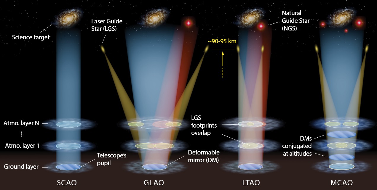 Image source: Adapted from Arseniy Kuznetsov, “Towards the next generation of tomographic AO-assisted instruments : Self-learning techniques for system optimization & science exploitation,” PhD thesis, Aix Marseille Université, 2024.
➡️ Regardless of the AO system, configuration always starts with defining the telescope and the atmospheric conditions.
The telescope
This section contains an exemple set of parameters related to the telescope.
[telescope]
[telescope]
TelescopeDiameter = 38.5
ZenithAngle = 30.0
ObscurationRatio = 0.28
Resolution = 480
to the pupil:
# path to the pupil model in .fits file - optional (if provided, the pupil model is interpolated) - default: ''
PathPupil = 'data/EELT480pp0.0803m_obs0.283_spider2023.fits'
PupilAngle = 0.0
to additional aberrations (in the main path or NCP):
PathStaticOn = '../P3/aoSystem/data/ELT_CALIBRATION/CombinedError_Wavefront_nm.fits'
PathApodizer = ''
PathStatModes = ''
or:
# extra error in the science FoV (error not included in TIPTOP like NCPA, optics quality, ...)
extraErrorNm = 160
extraErrorExp = -2
extraErrorMin = 0
# extra error in the technical FoV  (error not included in TIPTOP like NCPA, optics quality, ...)
extraErrorLoNm = 132
extraErrorLoExp = -2
extraErrorLoMin = 0
to windshake and additional tilt jitter:
# ELT tip & tilt wind shake when wind speed on M2 is 8 m/s
windPsdFile = 'data/morfeo_windshake8ms_psd_2022_1k.fits'
# jitter_FWHM --> 10 nm RMS tip error is 0.505arcesc
jitter_FWHM = 3.5
to the size of the technical field:
TechnicalFoV = 160.0
and to the global focus control:
# ground layer focus is controlled with NGS WFS
glFocusOnNGS = True
The atmosphere
This section contains an exemple set of atmospheric parameters - seeing (or r0), L0, Cn2 profile and wind profile - for an atmosphere modeled with 10 layers.
[atmosphere]
[atmosphere]
Wavelength = 500e-9
Seeing = 0.8
L0 = 22.0
Cn2Weights = [0.59, 0.02, 0.04, 0.06, 0.01, 0.05, 0.09, 0.04, 0.05, 0.05]
Cn2Heights = [30, 140, 281, 562, 1125, 2250, 4500, 7750, 11000, 14000]
WindSpeed = [6.6, 5.9, 5.1, 4.5, 5.1, 8.3, 16.3, 10.2, 14.3, 17.5]
WindDirection = [0., 0., 0., 0., 90., -90., -90., 90., 0., 0.]
The adaptive optics system
🔵 SCAO: Single Conjugate Adaptive Optics
For a SCAO system (using only one guide star), the configuration of the ..ini file (.ini) depends on the type of guide star
✴️ Natural Guide Star (NGS)
If the guide star is a NGS, you must include and complete the following sections: [sources_HO] and [sensor_HO].
-
[sources_HO]contains information about the NGS used for wavefront sensing, for example:[sources_HO]
# Sensing wavelength for HO modes in meters - required
Wavelength = 950e-9
# list of polar coordinates of the guide stars sources; zenith in arcsec and azimuth in degrees - optional - default [0.0]
Zenith = [0.0]
Azimuth = [0.0]
# altitude of the guide stars (0 if infinite) - optional - default: 0.0
Height = 0.0 -
[sensor_HO]contains information about the wavefront sensor configuration.
For example, in the case of a Shack-Hartmann wavefront sensor:Shack-Hartmann wavefront sensor -
[sensor_HO][sensor_HO]
WfsType = 'Shack-Hartmann'
Modulation = None
PixelScale = 832
FieldOfView = 6
Binning = 1
NumberPhotons = [100.0]
SigmaRON = 0.2
ExcessNoiseFactor = 2.0
# CoG computation algorithm - optional -defaut:'wcog'
Algorithm = 'wcog'
# Number of pixels for windiwing the low order WFS pixels - optional - default: 2
WindowRadiusWCoG = 2
NumberLenslets = [40]or a Pyramid wavefront sensor:
Pyramid wavefront sensor -
[sensor_HO][sensor_HO]
# WFS type - optional - default : Shack-Hartmann
WfsType = 'Pyramid'
# Spot modulation radius in lambda/D units for pyramid WFS - optional - default : None
Modulation = 3
# HO WFS pixel scale in [mas] - required
PixelScale = 220
# Number of pixels per subaperture - required
FieldOfView = 600
# Flux return in [nph/frame/subaperture] - required
NumberPhotons = [500]
# read-out noise std in [e-] - required
SigmaRON = 1.0
# dark current[e-/s/pix] - optional - default: 0.0
Dark = 0.2
# Sky background [e-/s/pix] - optional - default: 0.0
SkyBackground = 0.6
# excess noise factor - optional - default: 2.0
ExcessNoiseFactor = 1.0
# Number of WFS lenslets - required
NumberLenslets = [100]✏️Note: for a NGS only system, only the HO part is used.
✳️ Laser Guide Star (LGS)
If the guide star is a LGS, you must include and complete the following sections: [sources_HO], [sensor_HO] and [sources_LO], [sensor_LO]
-
[sources_HO]contains information about the LGS used for wavefront sensing, for example:[sources_HO]
Wavelength = [589e-9]
Zenith = [0.0]
Azimuth = [0.0]
Height = 90000 -
[sensor_HO]contains information about the wavefront sensor configuration.
For example, in the case of a Shack-Hartmann wavefront sensor:Shack-Hartmann wavefront sensor -
[sensor_HO][sensor_HO]
WfsType = 'Shack-Hartmann'
Modulation = None
PixelScale = 832
FieldOfView = 6
Binning = 1
NumberPhotons = [100.0]
SigmaRON = 0.2
ExcessNoiseFactor = 2.0
# CoG computation algorithm - optional -defaut:'wcog'
Algorithm = 'wcog'
# Number of pixels for windiwing the low order WFS pixels - optional - default: 2
WindowRadiusWCoG = 2
NumberLenslets = [40] -
[sources_LO]contains information about the NGS used for estimating the residual jitter, for example:[sources_LO]
Wavelength = [1650e-09]
Zenith = [0.0]
Azimuth = [0.0] -
[sensor_LO]contains information about the wavefront sensor configuration — by default, a Shack-Hartmann wavefront sensor.Wavefront sensor -
[sensor_LO][sensor_LO]
PixelScale = 16.0
FieldOfView = 100
Binning = 1
NumberPhotons = [100.0]
SpotFWHM = [[0.0]]
SigmaRON = 0.5
Dark = 40.0
SkyBackground = 120.0
Gain = 1.0
ExcessNoiseFactor = 1.3
# note 2x2 is required to provide focus control
# (see glFocusOnNGS in telescope section)
NumberLenslets = [2]
Algorithm = 'wcog'
WindowRadiusWCoG = 'optimize'
ThresholdWCoG = 0.0
NewValueThrPix = 0.0
noNoise = False
filtZernikeCov = True
🔘 The deformable mirror
The deformable mirror is used to achieve wavefront control and correction. The [DM] section contains the following parameters:
[DM]
[DM]
# DM actuators pitch in meters - required
NumberActuators = [80]
# DM actuators pitch in meters - required
DmPitchs = [0.38]
# DM influence function model - optional - default: 'gaussian'
InfModel = 'gaussian'
# DM influence function model  mechanical coupling- optional - default: [0.2]
InfCoupling = [0.2]
# DM altitude in m - optional - default: [0.0]
DmHeights = [600.0]
# Zenith position in arcsec - optional - default: [0.0]
OptimizationZenith = [0]
# Azimuth in degrees - optional - default: [0.0]
OptimizationAzimuth = [0]
# Weights - optional - default: [1.0]
OptimizationWeight  = [1]
# Matrix Conditioning - optional - default: 1e2
OptimizationConditioning = 1.0e2
# Number of reconstructed layers for tomographic systems - optional - default: 10
NumberReconstructedLayers= 10
# Shape of the AO-corrected area - optional - default: 'circle'
AoArea = 'circle'
📟 The real time controler
This section contains the details about the control parameters, frame rate and delay. If the system includes both LGS and NGS, this section must specify parameters related to both the HO part and LO parts.
[RTC]
[RTC]
# HO loop gain - required
LoopGain_HO = 0.5
# HO loop frequency in [Hz] - required
SensorFrameRate_HO = 500.0
# HO loop frame delay - required
LoopDelaySteps_HO = 1
# ❗Optionnal - if LO part simulated
# LO loop gain
LoopGain_LO = 'optimize'
# LO loop frequency
SensorFrameRate_LO = 500.0
# LO loop frame delay
LoopDelaySteps_LO = 2
🟢 LTAO: Laser Tomography Adaptive Optics
For an LTAO system with multiple LGSs, compared to a SCAO system with only one LGS, the Zenith and Azimuth parameters in the [sources_HO] section, as well as NumberPhotons and NumberLenslets in [sensor_HO] section, are lists with multiple elements.
🎛️ The wavefront sensor
As for the SCAO system, when both LGSs and NGS are present, the [sources_LO] and [sensor_LO] sections must be added. By default, the wavefront sensor specified in the [sensor_LO] section is a Shak-Hartmann wavefront sensor.
🔘 The deformable mirror
Like for a SCAO system.
📟 The real time controler
Similar to a SCAO involving both LGS and NGS.
🟤 GLAO: Ground Layer Adaptive Optics
🎛️ The wavefront sensor
Like for a LTAO system.
🔘 The deformable mirror
Like for SCAO and LTAO systems.
📟 The real time controler
Similar to a SCAO involving both LGS and NGS, or a LTAO system.
🟣 MCAO: Multi Conjugate Adaptive Optics
For an MCAO system with multiple LGSs and NGSs, the following parameters are specified as lists with multiple elements: Zenith, Azimuth in both the [sources_HO] and [sources_LO] sections, as well as NumberPhotons and NumberLenslets in both th [sensor_HO] and [sensor_LO] sections.
For example, in the case of six LGSs and three NGSs:
[sources_HO], [sensor_HO] and [sources_LO], [sensor_LO]
[sources_HO]
Wavelength = [589e-9]
Zenith = [45, 45, 45, 45, 45, 45]
Azimuth = [0, 60, 120, 180, 240, 300]
Height = 90e3

[sources_LO]
Wavelength = [1650e-9]
Zenith = [66.6, 79.3, 69.0]
Azimuth = [221.7, 321.2, 106.6]

[sensor_HO]
WfsType = 'Shack-Hartmann'
Modulation = None
NumberLenslets = [68, 68, 68, 68, 68, 68]
PixelScale = 1200
FieldOfView = 14
NumberPhotons = [500, 500, 500, 500, 500, 500]
SpotFWHM = [[2500.0, 2500.0, 0.0]]
WindowRadiusWCoG = 6
SigmaRON = 3.0
Algorithm = 'wcog'
addMcaoWFsensConeError = True

[sensor_LO]
PixelScale = 8.0
FieldOfView = 200
Binning = 1
NumberPhotons = [172000, 987, 5180]
SpotFWHM = [[0.0, 0.0, 0.0]]
SigmaRON = 0.5
Dark = 40.0
SkyBackground = 120.0
Gain = 1.0
ExcessNoiseFactor = 1.3
NumberLenslets = [1, 1, 1]
Algorithm = 'wcog'
WindowRadiusWCoG = 'optimize'
ThresholdWCoG = 0.0
NewValueThrPix = 0.0
noNoise = False
filtZernikeCov = True
🔘 The deformable mirror
For an MCAO system with multiple DMs, compared to the previously described systems, the following parameters in the [DM] section - NumberActuators, DmPitchs, InfCoupling and DmHeights - are specified as lists with multiple elements.
For example, in the case of three DMs:
[DM]
NumberActuators = [80, 30, 35]
DmPitchs = [0.5, 1.4, 1.4]
InfModel = 'gaussian'
InfCoupling = [0.2,0.2,0.2]
DmHeights = [600 , 6500, 17500]
OptimizationZenith = [0, 30, 30, 30, 30, 30, 30, 30, 30, 80, 80, 80, 80, 80, 80, 80, 80]
OptimizationAzimuth = [0 , 0 , 45 , 90 , 135 , 180 , 225 , 270 , 315 , 0 , 45 , 90 , 135 , 180 , 225 , 270 , 315]
OptimizationWeight = [10 , 20 , 20 , 20 , 20 , 20 , 20 , 20 , 20 , 1 , 1 , 1 , 1 , 1 , 1 , 1 ,1]
OptimizationConditioning = 1.0e4
NumberReconstructedLayers = 10
AoArea = 'circle'
📟 The real time controler
Similar to a SCAO involving both LGS and NGS, or a LTAO system.