TipTop - Error Terms Coverage
TipTop is an analytical AO PSF simulation tool that generates the long-exposure PSF by convolving a High-Order (HO) PSF with a Low-Order (LO) jitter kernel.
It covers the main AO error terms that can be expressed as spatio-temporal PSDs, but it does not include all telescope, instrumentation or calibration effects handled by a full end-to-end simulator.
Additional residuals can be introduced manually through the user-defined extra error terms (see the Understanding Additional Error Terms in TipTop tutorial).
1. HO Error Terms
The HO part is computed based on an estimation of the Power Spectral Density (PSD) of the the AO-corrected residual phase. This PSD is decomposed into several terms, which are assumed to be independent.
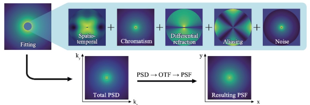 Summary of the different PSDs used in the HO part of TIPTOP. The first one is the fitting term, followed by temporal, noise, aliasing, etc. All PSDs are then summed and converted into the HO PSF.
(source: Neichel et al., "TipTop: toward a single tool for all ELT instrument’s PSF prediction", Adaptive Optics Systems IX, 2024)
🔽 HO Error Breakdown
✔️ Fitting error
Uncorrected high-spatial frequencies outside the AO/DM control region, i.e. above the DM cutoff set by the actuator pitch. Depends mainly on the actuator pitch and on the atmospheric seeing (through r0) at the AO reference wavelength, and is only weakly sensitive to the outer scale (L0).
Implemented in → fittingPSD()
Added to total PSD in → powerSpectrumDensity()
✔️ Aliasing error
High-spatial frequencies that are aliased owing to the WFS spatial sampling. Appears at lower spatial frequencies in the reconstructed phase. The aliasing PSD is computed using a SCAO formulation and reused for all directions without explicit projection through the tomographic reconstructor or DM projector. This is an approximation, but in practice the PSF shape is weakly sensitive to it.
Implemented in → aliasingPSD()
Added to total PSD in → powerSpectrumDensity()
✔️ Noise Error
Noise introduced by the WFS (detector, shot noise, background) that creates a signal that propagates
through the AO loop and affects the PSF. he model accounts for the (tomographic) wavefront reconstruc-
tion and the AO loop temporal model.
The noise variance is either computed from WFS characteristics or provided directly by the user (sensor_HO.NoiseVariance parameter).
Implemented in → noisePSD()
✔️ Spatio-Temporal error
Refers to the spatial error (wavefront reconstruction, tomography, SCAO anisoplanatism, DM projections,
LGS cone effect, MCAO LGS volume loss) that is combined with the temporal error (loop bandwidth, delays)
into a single term.
The user must
define the positions and altitude (for LGSs) of guide stars, as well as the altitude conjugations/actuators
pitch of the DM and the optimization directions. The tomographic error is calculated in the context of
pseudo-open-loop command (POLC) and Minimum Mean Square Reconstruction (MMSE) only.
All applied inside powerSpectrumDensity() before summation.
TipTop does not output a separate “tomography term” in HO breakdown (it only exists inside the spatio-temporal PSD).
✔️ Chromatic error
TipTop considers two PSD terms related to wavelength dependence:
-
Chromatism
Models the phase error due to the refractive-index difference between: (1) WFS/GS wavelength, and (2) science PSF wavelength.
Implemented in →chromatismPSD() -
Differential atmospheric refraction
Anisoplanatic-like PSD arising when science and guide stars are observed at different wavelengths and zenith angles. The refractive index of humid air is computed using a rigorous two-model approach introduced in [P3 v1.5.2]: the Ciddor (1996) model for wavelengths below 1.3 µm, and the Mathar (2006) model for longer wavelengths (J/H/K through N bands), both accounting for temperature, pressure, and relative humidity. This replaces the earlier simplified dispersion approximation.
Implemented in →differentialRefractionPSD()usingairRefraction.MatharAirRefraction
Both are added to the HO PSD only when the configuration activates them.
2. LO Error Terms
The LO module follows the method of Plantet et al. 2018.
It computes a jitter variance, converts it into a Gaussian kernel, and convolves it with the High-Order PSF to produce the final PSF delivred to the user.
The residual jitter is considered as the quadratic sum of 3 independent terms: (1) Windshake and vibrations, (2) Tomographic error for multi-NGS or off-axis NGS AO systems and (3) Noise propagation.
🔽 LO Error Breakdown
✔️ Windshake & Vibrations
TipTop can ingest a PSD of tip/tilt disturbances due to wind shake/vibration (see (telescope.windPsdFile parameter)). These disturbances are filtered by the closed-loop transfer function.
If no vibration file is provided, the vibration term is set to zero (Absence of vibration input ⇒ 0 nm residuals).
✔️ LO Tomography / Anisoplanatism
When multiple NGS are used for tip–tilt sensing, their geometry leads to a tomographic reconstruction error on tip–tilt modes. This residual corresponds to the difference between the turbulence seen by the NGS and the science target. For a single NGS, the residual jitter becomes the classical anisoplanatism error.
✔️ Noise error
The noise error corresponds to the propagation of the NGS sensors’ noise (photon noise, detector noise. . . ) through the LO loop.
TipTop estimates the noise contribution from each NGS using the actual PSF quality predicted at the NGS location, derived from the HO residuals. The PSF is converted into a slope error using a Gaussian spot model (Plantet et al. 2018), and propagated through an integrator loop, whose gains are automatically optimized.
For a single NGS, this filtered noise is used directly; for multiple NGS, the noise is first propagated through the tomographic reconstructor.
🟢 Final Jitter Kernel
After summing windshake, tomographic error, and propagated noise, TipTop converts the total Tip-Tilt variance into a Gaussian kernel (circular or elliptical based on the covariance). This kernel is expressed in milliarcseconds (FWHM), and it is convolved with the HO PSF (in tiptop.baseSimulation.finalConvolution()) to produce the final AO PSF delivered to the user.
📊 TipTop Error Coverage — General Overview
| Category | Error Source | TipTop? | Notes |
|---|---|---|---|
| HO | DM Fitting | ✔️ | HF fitting included in same PSD |
| Aliasing | ✔️ Approx. | SCAO formula reused | |
| WFS Noise | ✔️ | Propagated through reconstructor + controller | |
| Spatio-Temporal Reconstruction | ✔️ | MMSE/POLC + controller filtering | |
| Chromatism | ✔️ | WFS/science λ refractive index mismatch | |
| Differential Refraction | ✔️ | Wavelength + zenith angle anisoplanatism — rigorous Ciddor/Mathar model (since P3 v1.5.2) | |
| Cone Effect | ✔️ | Layer stretching + volume loss PSD | |
| LGS cone effect / MCAO volume | ✔️ | Dedicated PSD | |
| Telescope / Instrument Static | ⚙️ User | If user supplies static OTF/OPD maps | |
| Extra PSD | ⚙️ User | Via optional extra error parameters | |
| LO | Windshake & vibrations | ⚙️ Optional | Requires PSD file (telescope.windPsdFile) |
| Noise Propagation | ✔️ | Noise estimated using PSF from HO | |
| Tomography | ✔️ | Reduces to anisoplanatism if single NGS | |
| Extra Jitter | ⚙️ User | jitter_FWHM manual input in mas, convolved as a kernel | |
| Not included | Dome Seeing | ❌ | Not modeled |
| Low-Wind effect | ❌ | Not modeled | |
| WFS spot truncation | ❌ | No elongated sodium truncation | |
| Sodium profile variability | ❌ | Fixed sodium profile | |
| Post-focal DM Vibrations | ❌ | Telescope vibration only | |
| Calibration errors (misregistration, RTC updates) | ❌ | No engineering calibration |
🚧 This page is currently being updated.
📌 Interpreting the TipTop Error Breakdown Output
When a TipTop simulation finishes, if the key word getHoErrorBreakDown is set to True, the console prints a detailed wavefront error budget.
Each line corresponds to a specific term of the HO or LO model we described earlier.
🧩 Meaning of Each Term
🔽 Expand Table
| Breakdown Line | Meaning | Model Source | Type |
|---|---|---|---|
| Maréchal Strehl | Strehl computed using the Maréchal approximation at science λ | Uses total WFE | Output metric |
| Residual wavefront error | Quadratic sum of all HO + LO residuals in nm | After HO+LO modeling | Total |
| NCPA residual | Static uncorrected aberration provided by user (zCoefStaticOn or OPD map) | Added as static OTF/OPD | Static (user-specified) |
| Fitting error | DM cutoff (uncontrolled HF turbulence) | ||
fittingPSD() | HO | ||
| Differential refraction | Chromatic anisoplanatism (different λ, zenith angle). Refractive index computed with Ciddor (1996) for λ < 1.3 µm and Mathar (2006) for λ ≥ 1.3 µm, accounting for T, P and humidity. | ||
differentialRefractionPSD() | HO | ||
| Chromatic error | Refractive index mismatch between WFS and science wavelengths | ||
chromatismPSD() | HO | ||
| Aliasing error | High frequencies folded by WFS sampling | ||
aliasingPSD() (SCAO approximation) | HO | ||
| Noise error | Photon + detector noise propagated through reconstructor + controller | ||
noisePSD() | HO | ||
| Spatio-temporal error | Combined reconstruction + servo filtering (tomography + lag) | Inside powerSpectrumDensity() | HO |
| Mcao Cone | MCAO LGS volume loss term | Automatic in MCAO mode | HO |
| Extra error | User extra PSD added to HO halo | extraError* | HO (user) |
| Bottom lines | Meaning | Notes |
|---|---|---|
| Sole servoLag error | Temporal part ONLY of HO error (ideal infinite reconstructor) | Helps tune controller |
| Sole reconstruction error | Pure spatial tomography ONLY (no controller effect) | Useful for reconstructor performance |
| Sole tomographic error | MCAO/NGS/LGS geometry + reconstructor without lag or noise | Matches Plantet et al. “pure tomography” |
The “Sole …” diagnostic lines are not added to the total wavefront error. They are isolated components useful for AO tuning and performance analysis.